

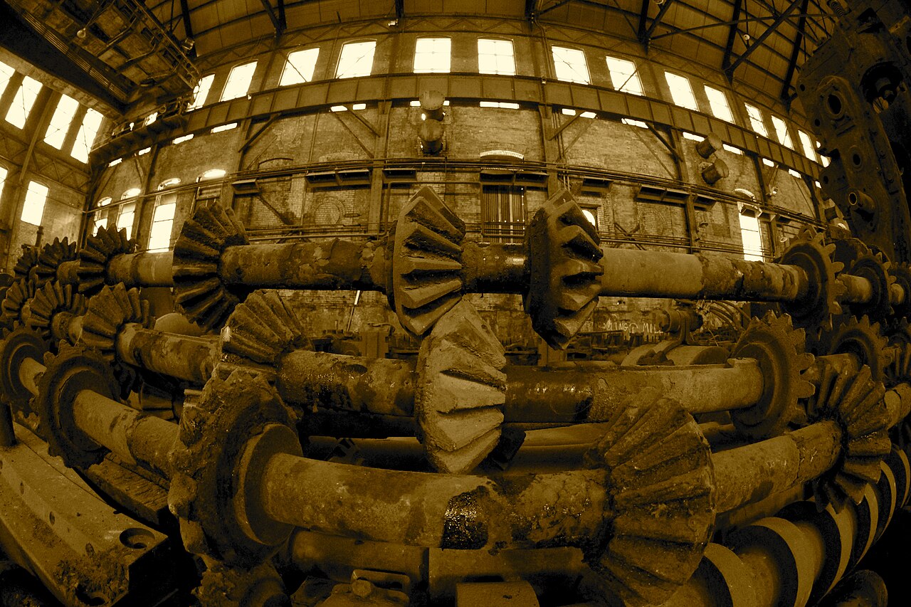
A double helical gear — herringbone, when the two tooth sets meet in a continuous chevron — carries two opposing helical halves on one body so their axial forces cancel: each half produces a thrust of nominal magnitude Fa = Ft tan β, and the opposite hand reverses its direction. Net external thrust is therefore close to zero, which is why the design is chosen where thrust-bearing capacity or axial deflection would otherwise limit a single helical gear. The cancellation is nominal, not absolute: lead error, misalignment and unequal load sharing leave a residual thrust the bearings must still carry.
This guide covers thrust balance, helix angle and axial overlap, the relief-groove trade-off, mounting, failure modes and manufacturing routes, including where metal injection molding (MIM) stops being a sensible option.
Why Double Helical Gears Exist: Cancelling Axial Thrust
A single helical gear runs smoother than a spur gear because teeth engage progressively, but the trade is an axial component: Fa = Ft tan β, with Ft the transmitted tangential force and β the helix angle. That thrust needs a thrust bearing, and it bends the shaft and housing, biasing contact toward one edge of the face width.
A double helical gear removes the problem at the source. The second set is cut with the opposite hand, so its axial component points the other way and the two nearly cancel: lighter axial location, no one-sided preload, and contact that stays spread across the full face width. That is why the design appears in rolling-mill drives, marine reduction gears and large industrial gear units where a big thrust bearing is unattractive.
Herringbone vs Double Helical: The Center Relief Question
Both names describe the same principle with a different center construction. A herringbone gear is essentially continuous, its two helices meeting at an apex to form a chevron; a double helical gear is cut as two sections separated by a relief groove. The choice is as much a manufacturing decision as a design one.
| Aspect | Herringbone (continuous chevron) | Double helical (center groove) |
|---|---|---|
| Center | Helices meet at an apex | Two halves split by a groove |
| Effective face width | Continuous across apex | Reduced by groove width |
| Tool access | Two passes plus blending | Clean run-out for hob or wheel |
| Deburring / inspection | Apex hard to reach | Groove gives a reference |
| Center stress | Apex form dependent | Controlled by groove radius |
The groove gives the cutting tool somewhere to run out: hobbing, shaping and grinding cannot pass a continuous apex without interference, so the transition is usually two passes blended together. A groove buys clean tool access, predictable deburring and a measuring reference, and relieves the stress concentration a sharp apex would create. The cost is interrupted contact — effective face width drops by the groove width, and load must transfer across a region carrying no flank.
Helix Angle and Axial Overlap Ratio
Helix angle is measured on the pitch cylinder and is not fixed by any accuracy standard: ISO 1328 governs how accurately a flank is made, not how the gear is proportioned. References commonly cite about 15° to 45°, with roughly 15° to 30° usual for helical gears and values above about 45° discouraged because sliding velocity, tooling difficulty and thrust sensitivity all rise.
Smoothness comes from axial overlap, εβ = b / px — the number of axial pitches covered by effective face width b, with px the axial pitch. A practical target is often εβ ≥ 1, so contact hands over before the previous pair leaves; 1.15 to 2.0 axial pitches is a common rule of thumb, not an acceptance criterion. In a grooved gear the overlap calculation should use the combined working width of the two halves with the interrupted groove region excluded and its load-transfer effect treated explicitly, not the overall blank width; total contact still depends on transverse contact ratio, profile accuracy, alignment and mesh stiffness.
Mounting and Axial Location
Because net thrust is small, the bearing arrangement simplifies: one typical pattern locates the shaft axially at one bearing and lets the other end float, absorbing thermal growth and residual thrust without preloading the housing. Two mistakes recur — designing for zero thrust, then finding a misaligned housing biases load onto one half that runs loud with reversed contact; and forgetting that radial loads, overturning moments and thermal movement are unchanged and still need controlling. A gear left free to float finds its own balance between halves, but it also moves under load, and the mesh must tolerate that without edge contact.
Materials, Heat Treatment and Failure Modes
These gears use the same gear steels as single helical equivalents: case carburizing and grinding where pitting resistance and surface hardness matter, nitriding where distortion must stay low on a finished gear, through hardening for moderate loads. Pinion and gear are normally specified as a hardness pair so the softer member wears predictably. Hardness and case-depth values are duty-specific and quoted on request.
- Relief groove stress concentration — the classic failure site; a generous radius and smooth blend matter more than nominal section.
- Face-width load bias from misalignment, producing edge pitting or tooth breakage.
- Pitting and micropitting driven by contact stress and oil film; case-hardened, ground flanks are the countermeasure.
- Scuffing at high sliding velocity with marginal lubrication — helix angle and lubricant choice are linked decisions.
- Apex pitch or profile error on continuous herringbone gears, often invisible in a runout check.
Manufacturing Routes and Where MIM Fits
The route follows the geometry. Hobbing is the volume workhorse, cutting each half in a separate pass; shaping reaches shoulders where a hob cannot run out; milling and broaching cover large or special forms; profile or generating grinding sets final accuracy after hardening.
| Route | Best fit | Limits to check |
|---|---|---|
| Hobbing | Volume helical halves | Hob run-out at groove or apex |
| Shaping | Shoulders, close-to-intercept | Cycle time, cutter clearance |
| Grinding | Hardened gears, fine grades | Distortion allowance |
| PM compaction | Small spur gears, high volume | Helical teeth compact less uniformly |
| MIM | Small gears, molded-in features | Helix ejection, lead error, distortion |
MIM sits at the small end of that map. Sintered and molded gears pay off when the part is small, volume is high and the tooth form can be made in one tool without secondary cutting — a spur gear with a molded bore and hub is close to ideal. A helix complicates the tool: the form must eject along the helix, parting lines cross flanks, and density, lead error and distortion must be validated on the real geometry. For double helical and herringbone parts MIM is feasible only in a narrow window — small module, small diameter, short face width, and a form the tool can release without a sliding core. Large-diameter, long-face-width double helical gears are not recommended for MIM: mold size, ejection and sintering distortion leave the stable window, and long-face helix and lead deviation is exactly what sintering scatter attacks first. Treat such a part as a capability trial, asking for density, runout, lead, profile and a functional mesh rather than a catalogue module figure.
Emitech's own MIM capability — company-specific rather than a general industry envelope — is 0.1–200 g part mass with 0.5–6 mm walls; Emitech-held as-sintered tolerances are ±0.3–0.5% of nominal (about ±0.025 mm under 3 mm), tightening to about ±0.01 mm where sizing or CNC finishing is applied. See the MIM capabilities page. Small molded gears are covered in MIM small gears, the process chain in the MIM gears manufacturing guide, and where a helical form cannot be molded the usual answer is a molded blank with cut teeth as a secondary operation.
Drawing and Acceptance Notes
The drawing must describe two tooth sets and their relationship, which is where most inspection disputes start. Call accuracy out by standard, edition and parameter rather than a vague “gear accuracy”: ISO 1328-1 defines flank accuracy grades numbered 1 through 11 with tolerance increasing as the grade number rises, and the drawing should name the controlled parameters and say whether they apply per half or to the whole gear. Contact marking diagnoses alignment, it does not replace measurement, so state load condition, marking method and acceptance authority beside any coverage figure.
- Helix angle and hand for each set, plus a tolerance on helix angle itself.
- Relief groove width, depth and corner radii, or the apex form — this defines effective face width.
- Accuracy grade with standard and edition, and the measured parameters rather than one aggregate number.
- Contact pattern check conditions and acceptance authority.
- Functional mesh test at operating centre distance, checking transmission error and noise.
Frequently Asked Questions
Q: Do double helical gears really produce zero axial thrust?
Only ideally. Each half produces a thrust of nominal magnitude Fa = Ft tan β in opposite directions, so net external load is near zero, but lead error, misalignment and unequal load sharing leave a residual. Size the axial location for that residual, not for zero.
Q: When should a relief groove be used instead of a continuous herringbone form?
Use a groove when teeth will be hobbed, shaped or ground, or when the apex would be hard to deburr and inspect. Use a continuous chevron only when the process can hold the apex without interference or pitch error. The groove costs effective face width, which feeds into axial overlap.
Q: What helix angle and face width should I specify?
About 15° to 30° per half is the usual band, with values near 45° generally discouraged. Size face width so εβ = b / px reaches at least about 1, with 1.15 to 2.0 axial pitches a rule of thumb, then confirm against transverse contact ratio and actual duty.
Q: Can a small double helical gear be made by MIM?
Sometimes, but only with small module, small diameter, short face width and a form the tool can eject along the helix without a sliding core. Large-diameter, long-face-width double helical gears are not recommended for MIM. Ask for a capability trial covering density, runout, lead, profile and a functional mesh.
Q: How should accuracy and contact pattern be specified?
Name the standard and edition, for example ISO 1328-1 grades 1 to 11 with tolerance increasing with grade number, list the controlled parameters, and state whether they apply per half or to the whole gear. For contact marking, specify load condition, method and acceptance authority.
Double helical and herringbone gears are a thrust-management solution first and a gear-cutting exercise second: center construction, helix angle and face width all follow from how much residual axial load the housing can absorb.
If you are weighing a molded gear against a cut one for a small helical part, send the drawing and duty cycle through the contact page. Emitech reviews the geometry for MIM feasibility, including where a chevron or groove makes molding impractical, and quotes with DFM feedback within 24 hours.
Precision Metal Parts from Emitech
Nanjing Emitech delivers MIM, CNC machining, and custom metal parts. MIM services · Request a quote