

Identify a MIM part by a bundle of clues, never one: molded witnesses (parting line, ejector pin marks, gate marks), a matte as-sintered surface around 0.8 µm Ra, near-full density with typically under 3 % residual porosity in ferrous grades, and — when it matters — a fine, uniform sintered microstructure under the microscope.
This page is for engineers, quality staff and reverse engineers holding a small metal part and asking which process made it. It walks the identification in the order an experienced eye works: surface witnesses first, weight and density second, competing processes ruled out third, microstructure as the confirmation. Each clue is stated with its limits — finishing can erase witnesses, and no single mark proves anything on its own.
Start With the Three Molded Witnesses
MIM begins as an injected green part, so the surface carries the same witnesses plastic injection molding leaves: a parting line where mold halves meet, ejector pin marks where the soft green part was pushed out, and a gate mark where feedstock entered the cavity. On MIM these are usually subtle — the parting line is typically a fine protruding seam, with cited witness heights on the order of 0.0003–0.001 in, and ejector marks are minor witness rounds that grow more visible as tooling wears.
Treat the three witnesses as a fingerprint of the molding stage, not a verdict. A seam alone does not prove MIM — plastic parts, die castings and compacted powder parts can all carry parting lines — and cosmetic or secondary-finished MIM parts can hide their witnesses entirely. What the witnesses tell you is that the part was molded; the material and density evidence in the next sections is what pin the process to MIM specifically. How these marks form is covered in the MIM process guide.
| Surface witness | What it looks like on MIM | What it proves — and does not |
|---|---|---|
| Parting line | Fine protruding seam, often subtle; cited witness heights ~0.0003–0.001 in | The part was molded in split tooling; not unique to MIM |
| Ejector pin marks | Minor round witness flats on the B-side; more visible as tooling wears | Green part was ejected from a mold; also common to plastic molding |
| Gate mark | Small trimmed-entry witness where feedstock entered the cavity | Material was injected; location and size follow mold design |
| Matte as-sintered texture | Uniform matte finish, ~16–32 µin Ra (about 0.80 µm Ra) cited | No cutting tool engaged the face; consistent with sintering |
Read the As-Sintered Surface
Unfinished MIM surfaces are typically matte and uniform, without the directional texture of machining. Cited figures for as-sintered MIM surface roughness cluster around 16–32 µin Ra (about 0.80 µm Ra), and the texture is evenly distributed over molded faces rather than concentrated where a tool engaged.
Two cautions keep this clue honest. First, MIM is not always the rougher option — its as-sintered finish is often appreciably finer than most investment castings, so a smooth-ish matte part should not be dismissed as cast on texture alone. Second, many production MIM parts receive secondary finishing that overrides the as-sintered look entirely; see MIM surface finish options for what those processes do to the surface.
Weight and Density: Measure, Do Not Guess
MIM parts sit at near-full density — commonly 95–99 % of theoretical for the alloy, with ferrous MIM grades often cited at under 3 % residual porosity. That places them close to machined barstock in heft, far from the pressed-powder feel people sometimes expect. The pores that do exist are typically fine, rounded and isolated, which is why MIM parts are often impermeable to gases and liquids in normal service despite not being pore-free.
A hand weigh test proves little by itself: part volume, wall thickness and hollow geometry can dominate mass. The method that works is comparative — part weight against the computed solid volume for the identified alloy, checked against a known wrought or MIM baseline. A meaningful gap downward suggests a powder-based or cast route; agreement is consistent with (but does not alone prove) MIM. Typical density bands by alloy family are listed in the MIM materials properties reference.
Rule Out the Look-Alike Processes
Identification is mostly elimination. The four processes most often confused with MIM each fail a different test: die casting leaves gates and flash but in aluminum, zinc or magnesium alloys — a small steel or stainless part with molded witnesses is essentially never die cast; CNC machining shows cutter marks, sharp engaged edges and fixturing evidence instead of molded witnesses; investment casting shows cast texture, sprue remnants and often rougher finish than MIM at the same feature size; conventional powder compaction shows a pressed-powder surface, die-wall effects and shape limits from uniaxial pressing.
| Clue | MIM | Die casting | CNC machining | Investment casting | Powder compaction |
|---|---|---|---|---|---|
| First alloy check | Steels, stainless, Ti, soft magnetic | Al / Zn / Mg alloys | Any wrought alloy | Most alloys | Fe-based, bronze |
| Surface | Matte, molded witnesses | Cast skin, flash, gates | Cutter marks, sharp edges | Cast texture, sprue remnants | Pressed-powder look |
| Geometry | Small, intricate, 3D-freedom | Nonferrous, cored | Blocky, stock-removal | Shell-limited detail | Flat-pressed, 2D-biased |
| Density | 95–99 % theoretical | Dense as-cast (defects possible) | Full wrought density | Dense-ish, shrinkage risk | More porous, gradient |
| Microstructure | Fine sintered grains, isolated round pores | Dendritic cast structure | Wrought / heat-treated | Dendritic cast structure | Flatter pressed porosity |
Each pair is compared in depth on its own page: MIM vs CNC machining, MIM vs die casting, MIM vs investment casting and MIM vs conventional powder metallurgy.
Microstructure Confirms What the Eye Suspects
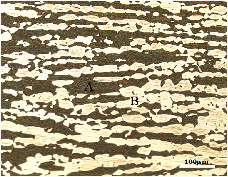
When the answer has to be certain — failure analysis, supplier dispute, counterfeit check — section and etch the part. A MIM microstructure shows a fine, uniform sintered grain structure with small, rounded, isolated pores: the signature of powder that was molded, debound and sintered. A die-cast or investment-cast part instead shows dendritic solidification structure; conventional press-and-sinter PM shows flatter, less uniform porosity with density gradients from one-sided pressing.
Read the porosity honestly. Some residual porosity is inherent to MIM, and its meaning depends on amount, size, connectivity and location — isolated microporosity in a non-critical zone is normal MIM, not a defect, while connected porosity at a load path is a process problem. Density measurement (Archimedes) gives a fast numerical cross-check on the metallographic read.
When the Part Is Polished, Plated or Machined
Secondary operations erase the easy clues. Polishing removes parting-line witness, plating masks matte texture, and machining reintroduces cutter marks on finished faces — so a finished MIM part can look, at a glance, like anything. The durable evidence survives: unmachined internal features still carry molding witnesses, density stays near-full wherever the original surface remains, and microstructure is untouched by every cosmetic treatment.
Work the same sequence on finished parts, weighted toward the later steps: find one as-molded face (inside a pocket, under a flange), run the weight-to-volume check, and escalate to metallography if the stakes justify it. What secondary operations do exist on MIM parts is cataloged in MIM parts surface treatment.
A Working Identification Workflow
In practice the identification collapses to three steps, escalating only as far as the decision needs. Step 1 — eyes and a loupe: molded witnesses, matte texture, alloy type, absence of toolpath marks; this separates MIM from machining and casting in most cases. Step 2 — numbers: weight against computed solid volume, density against the alloy band. Step 3 — metallography or a density measurement: the confirmation level for disputes and failure analysis.
Expect ambiguity at step 1 roughly as often as certainty — witnesses can be faint, finished or coincidental — which is why the discipline of the bundle matters: no single clue decides, and every positive MIM call should survive at least two independent lines of evidence.
Frequently Asked Questions
Q: How can you tell if a part is MIM?
Look for the bundle: molded witnesses (parting line, ejector pin marks, gate mark), a matte as-sintered surface around 0.8 µm Ra, near-full density, and a small intricate steel or stainless geometry. Confirm with metallography — fine sintered grains with rounded isolated pores — when the call has consequences.
Q: Do all MIM parts have ejector pin marks?
No. Marks are common because green parts must be ejected, but cosmetic requirements, secondary finishing and mold design can make them faint or keep them off visible faces. Absence of ejector marks does not rule MIM out.
Q: Can MIM be confused with die casting?
Rarely on material: die casting serves aluminum, zinc and magnesium, while a small part with molded witnesses in steel or stainless is essentially outside die casting’s alloy range. Confusion is more likely with investment casting or conventional powder compaction, which share the small-complex-metal space.
Q: Does porosity in a MIM part mean it is defective?
Not by itself. Ferrous MIM often carries under 3 % residual porosity as fine, isolated, rounded pores — normal for the process. What matters is amount, size, connectivity and location; connected porosity on a load path is a problem, isolated microporosity elsewhere is not.
Q: What test confirms MIM conclusively?
A sectioned, etched microstructure exam: fine uniform sintered grains with rounded isolated pores distinguish MIM from dendritic cast structures and from conventional press-and-sinter porosity. An Archimedes density measurement is the fast numerical cross-check.
Hold a part the clues point to and want a second opinion — or want to know whether a machined or cast part converts to MIM at your volume? Send the drawing through the contact page: Emitech reviews geometry, material and tolerance for MIM suitability within 24 hours.
Precision Metal Parts from Emitech
Nanjing Emitech delivers MIM, CNC machining, and custom metal parts. MIM services · Request a quote