

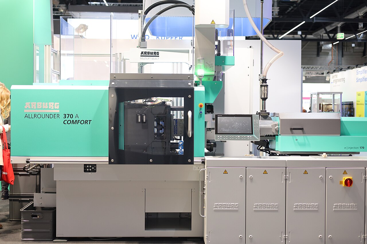
The green part defects that dominate MIM molding scrap are short shot, flash, weld lines, sink marks and internal voids, and demolding or handling damage — and because MIM feedstock is a highly powder-loaded compound, the same tool that would run clean in plastic can flash through clearances plastic cannot penetrate. Most of these molding defects respond to three levers: filling conditions (feedstock temperature, injection speed, venting), gate and runner design, and packing strategy held until gate freeze-off. The compounding factor is that green flaws are amplified downstream: during debinding and sintering the part contracts by a linear shrinkage that is typically about 12-20% depending on feedstock and sintering conditions, which turns thin green flash into hard metal burrs and exaggerates any molded-in density gradient into warpage.
Scope note: this page covers only the injection molding stage — feedstock entering the barrel to green part leaving the mold. Furnace-stage defects such as carbon pickup, distortion and blistering are treated in the sintering failure analysis, and the inspection gates that catch these flaws are covered under MIM quality control.
Why MIM Molding Defects Differ From Plastic Molding
Metal injection molding feedstock is a thermoplastic binder loaded with a high volume fraction of metal powder — typically on the order of 55-70 vol% solids in common systems. That loading changes the rheology: the compound is more abrasive to the tool, and it will penetrate very small clearances between mold plates, slides, core pins and shutoffs. Published MIM processing guidance is explicit that MIM is more flash-sensitive than ordinary thermoplastics for this reason, and that parting lines and shutoffs require unusually precise fit and maintenance.
The consequences are practical. First, an investigation should not stop at machine settings: with a worn or contaminated shutoff, no combination of pressure and clamp force produces a flash-free part. Second, correcting one defect can create another — more pressure fixes a short shot but can force feedstock through marginal clearances. Third, generic plastic-molding limits (flow-length ratios, shot-weight tolerances) do not transfer to MIM; feasible geometry depends on the powder grade, binder system, solids loading and gate design, so treat inherited numbers as development starting points, not specifications.
The Five Core Defects at a Glance
The table below maps each defect to where it appears, its typical causes, and the first corrective levers to try — a triage aid for a conversation with a molder, not a substitute for controlled trials on the actual tool.
| Defect | What you see | Typical causes | First corrective levers |
|---|---|---|---|
| Short shot | Incomplete cavity or missing feature; light part weight | Low feedstock temp / pressure / speed; long flow path; premature gate freeze-off; poor venting | Raise melt/mold temp in window; fill faster; improve venting; enlarge or relocate gate |
| Flash | Excess material at parting line, slides, cores, shutoffs, ejectors | Cavity pressure vs clamp; worn or contaminated shutoffs; misalignment; overpacking; high feedstock temp | Inspect and repair tool first; then adjust packing and temperatures; clamp force alone is not a fix |
| Weld line | Seam where flow fronts rejoin downstream of a hole, boss or core | Cold fronts meeting; trapped gas; unfavorable gate location | Relocate or enlarge gate; raise fill temp/speed in window; vent the meeting zone |
| Sink mark | Surface depression at thick sections, bosses, rib intersections | Shrinkage not packed out before gate freeze-off | Core thick sections; gate toward thick zones; extend hold until gate-seal study stabilizes weight |
| Void | Internal cavity, often with no visible surface indication | Solidified skin forcing shrinkage inward; sections above ~4 mm at heightened risk (feedstock-dependent) | Coring and wall balance; verify by sectioning or CT on first articles; lock packing recipe |
Two cautions on reading the table. Flash with machine settings "in range" almost always means the tool, not the process — worn shutoffs, parting-line damage, misalignment or trapped contamination. And sink marks and voids are related but not equivalent: a section can sink with no void, or hide a void with no visible sink.
Short Shot and Flash: The Filling Pair
A short shot is an incomplete cavity fill — a missing feature, a ragged flow end, a part that weighs light. The typical cause chain runs through insufficient feedstock temperature, injection pressure or speed, excessive flow length for the gate size, premature gate freeze-off, and inadequate venting that lets trapped air back-pressure the flow front. Corrective trials in molding references prioritize, in rough order: raise melt or mold temperature within the validated feedstock window, fill faster, improve venting, then enlarge or relocate the gate — attacking flow resistance before force-feeding the cavity.
Flash is feedstock that escaped the cavity: at the parting line, around slides or core pins, at shutoffs or ejector clearances. Besides excessive cavity pressure or clamp inadequacy, the usual suspects are worn or damaged shutoff surfaces, tool misalignment, excessive feedstock temperature, and overpacking. The published MIM guidance is blunt: increasing clamp force alone is not a reliable fix when the tool is worn or contaminated, and can damage the tool or machine. Verify the tool before turning the machine up.
These two defects pull against each other — the pressure that guarantees a complete fill is the pressure that finds every clearance in the mold. This is why gate and venting design dominate long-term flash control in MIM. Gate placement, sizing and runner balance are covered in the MIM gate and runner design guide; the balanced layouts and gate freeze behavior there are what make a filling window stable in production.
Weld Lines: When Meeting Flow Fronts Leave a Trace
Weld lines (also called knit lines) form wherever the flow splits around a core, hole, boss or insert and the fronts meet again downstream. In MIM the line is a visible seam on the green part, and its significance depends on the meeting temperature and pressure, entrained gas or contamination, the local geometry, and binder condition at the front. A visible line is not automatically a structural defect — but neither are weld lines always cosmetic; their effect must be judged against the service loading.
The corrective levers follow from the mechanism. If the fronts meet too cold, raising filling temperature or speed within the validated window and enlarging or relocating the gate restores front temperature; if the line is discolored or weak, the cause is often trapped gas, and the fix is venting at the meeting point rather than more pressure. Because the root cause differs, the correct change differs — cold-front weld lines, gas-trapped weld lines and jetting are three different problems that look similar on the green part.
The design-side lever is flow-path geometry: moving a hole, repositioning the gate so the weld line forms in a non-critical region, or adjusting wall transitions so fronts meet at higher pressure. These are DFM-level decisions, best made before the tool is cut — the DFM guidelines page covers the wall, draft and feature rules that prevent the problem classes a molder can only mitigate.
Sink Marks and Voids: The Packing Pair
Sink marks and internal voids share one mechanism: local volumetric shrinkage that could not be compensated by more feedstock before the gate froze. When the skin stays soft, the surface draws inward — a sink mark at thick sections, bosses and rib intersections. When a solidified skin holds the surface, the shrinkage goes inward instead — an internal void in the section core. Published processing guidance identifies sections above roughly 4 mm as a heightened void-risk region, though the threshold is feedstock-, geometry- and process-dependent rather than universal.
The prevention logic is therefore geometric before it is process-based: core out thick regions, balance wall thickness, and gate so that packing pressure reaches the thick sections while the gate is open. The process levers — packing pressure and hold time — are effective only until gate freeze-off; after freeze-off, more hold time does not reach the section and tends instead to add flash or molded-in stress. A gate-seal study that shows green part weight stabilizing across shots is the practical evidence that the packing window is doing its work.
Detection is the hard part: an internal void can exist with no surface indication, so visual inspection cannot certify a thick section. Sectioning or computed tomography on first-article parts, then a locked packing recipe, is the standard qualification path. Wall ranges that coring can address are part of the window discussed in the MIM size limitations guide.
Green Part Weight: The Monitoring Window
Green part weight is the primary shot-to-shot repeatability signal in MIM molding, but its limits must be understood. A stable weight trend proves that the same mass of feedstock entered the cavity each shot; it does not prove uniform local density, does not exclude internal voids, and does not certify debinding behavior. A capable monitoring plan reads the weight trend together with dimensions, visual condition, gate and runner condition, cushion, injection pressure, and mold and feedstock temperatures.
For a new tool and feedstock combination, weight control limits are established empirically: a capability run defines the natural shot-to-shot spread, the limits are set from that data, and any feedstock change — different lot, different powder chemistry, different solids loading — invalidates them, because feedstock variables directly change viscosity, filling, shrinkage and final density. Emitech's machine-specific limits and sampling plans are set per tool and quoted on request.
Equally important is attributing damage to the right stage. Cracks, deformation, ejection damage and gate-removal damage are frequently introduced during demolding or handling rather than filling — a cracked green part is not automatically a molding-parameters problem, and adjusting the injection profile will not fix a bruised ejector. Sorting by stage comes before any parameter change; the stage-gate framework for that triage is laid out in the MIM quality control page.
Why Green Defects Get Worse After Sintering
MIM shrinkage happens mainly in debinding and sintering, not in the mold: the green part contracts by a linear shrinkage that is typically about 12-20% depending on feedstock and sintering conditions, as binder leaves and the powder skeleton densifies toward 95-99% of theoretical density. That contraction amplifies everything molding put into the part. Thin flash becomes a metal burr at finished scale — hard, attached, and expensive to remove. Weld lines and density gradients become dimensional distortion; a marginal green weight drift becomes a finished-dimension drift across the lot.
This amplification is why MIM molders treat green part inspection as a control point rather than a formality, and why leaving flash for later removal is not a sound disposition: green flash that survives to sintering damages handling, debinding fixtures and finishing operations downstream. The full catalog of furnace-stage failure modes — and the boundary between a molding root cause and a sintering root cause — is in the sintering failure analysis.
Frequently Asked Questions
Q: How do I tell a MIM short shot from a venting or gate-freeze problem?
Work from the flow end backward. A ragged front in the last-to-fill region with settings in range points to trapped air — improve venting first. A fill that stalls progressively across shots points to temperature or feedstock condition drift. A consistently short same-feature pattern points to flow-length or gate-size limits, which is a tooling conversation, not a settings one.
Q: Flash appears although injection pressure and clamp force are within settings — what now?
Inspect the tool before touching the machine. Worn or damaged shutoff surfaces, parting-line wear, misalignment and trapped contamination all let highly loaded MIM feedstock through clearances plastic would not penetrate. Increasing clamp force on a worn tool is not a reliable fix and can damage the tool or machine.
Q: How are green part weight control limits set for a new MIM tool?
Empirically, from a capability run: the natural shot-to-shot spread defines initial limits, and a gate-seal study confirms when part weight stabilizes across shots. The limits are specific to the tool and feedstock lot; a feedstock change invalidates them. Emitech sets limits per tool and quotes specifics on request.
Q: Can a visible weld line on a green part be accepted?
Sometimes — it depends on meeting temperature and pressure, trapped gas, geometry, and the service loading the line will see. A visible line is not automatically a structural failure, but accepting one in a load-bearing region without characterization is not recommended; judge the line against the application, do not assume it is cosmetic.
Q: Why not just grind the flash off after sintering?
Because sintering amplifies it: a thin green flash line becomes a hard metal burr bonded at finished scale, and removing it adds a grinding operation to every part in the lot. Green-stage flash is not harmless before sintering either — it can damage handling and debinding. Fixing the tool or packing upstream is almost always cheaper than a permanent deburring operation.
Most MIM molding defects trace back to three decidable points: the tool (gate, venting, shutoff condition), the window (filling and packing conditions validated for the feedstock), and the geometry (walls and coring that do not demand heroic packing). If a drawing is still open, the least costly fixes are available now — send it via the contact page for DFM feedback on gate placement, wall balance and defect risk before the mold is cut, with a quotation returned within 24 hours.
Precision Metal Parts from Emitech
Nanjing Emitech delivers MIM, CNC machining, and custom metal parts. MIM services · Request a quote