

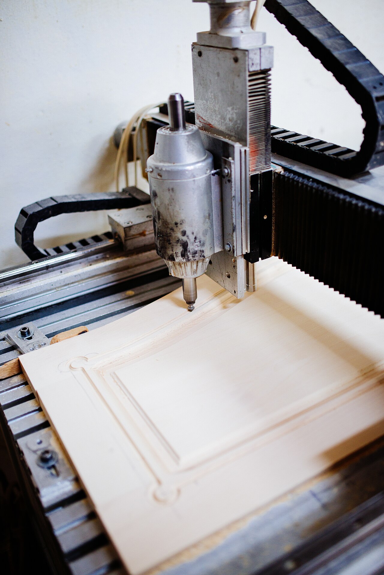
Most MIM parts ship as-sintered at ±0.3–0.5% of nominal dimension (about ±0.025 mm on features under 3 mm), and need no post-processing at all. When specific features must be tighter, flatter, or smoother than the sintering furnace delivers, the fix is a targeted secondary operation — sizing or coining to correct geometry by forming, or grinding, CNC machining, drilling and tapping to remove metal — applied only to the critical faces, not the whole part. With sizing or CNC finishing, treated features reach approximately ±0.01 mm. The skill in MIM secondaries is choosing the lightest operation that closes the gap, because every added step costs cycle time and adds handling risk.
This page is the full menu of what happens after a part leaves the sintering furnace: what each operation does, which features it suits, what tolerance improvement to expect, and where each one should be avoided. Surface treatment, heat treatment and HIP each have their own dedicated pages and are only pointed to here.
The Secondary Operations Menu
Metal injection molding is a near-net-shape process: parts emerge from sintering at 95–99% of theoretical density, with functional geometry largely formed. Secondary operations exist for the gap between that baseline and what the application demands on a handful of features. They split into two families with fundamentally different physics.
- Forming corrections — sizing and coining press or calibrate the part in a die. No metal is removed; the material is plastically displaced to correct flatness, roundness, or profile on selected faces.
- Material removal — grinding, CNC turning and milling, drilling, reaming, and tapping all cut metal away to create or improve features that molding could not hold.
- Property and surface routes — heat treatment, HIP, tumbling, polishing and plating change properties or appearance rather than dimensions; see the surface finish page for those options.
Published guidance is consistent on one point: secondaries are normally reserved for genuinely critical features rather than applied across the part, because broad post-processing erodes the cost advantage that justified MIM in the first place. Emitech runs these operations in-house — 24 sizing presses and 14 grinding machines alongside the MIM injection and sintering lines — so formed and machined features stay under one process control, as listed on the MIM capabilities page.
Sizing and Coining: Correcting Geometry Without Cutting
Sizing (also called coining or calibration) places the sintered part in a die and applies pressure to restore or improve a dimension. It is the first choice when the part is already close to net shape and the problem is distortion-related: a flange that bowed in sintering, a bore that went slightly out of round, a boss height that drifted. Because it is a die operation, it is fast and repeatable — but it only works on features the die can reach and the alloy will flow to correct.
Typical targets are flat faces, bosses, holes, and mating surfaces where the as-sintered ±0.3–0.5% band misses the drawing requirement. Some published guides place sized features around IT 7–8 versus the as-sintered IT 8–11 band; those figures vary by source and geometry, so treat them as directional rather than guaranteed. Emitech's measured capability after sizing is approximately ±0.01 mm on treated features.
- Choose sizing when: the error is shape or distortion (flatness, roundness, profile) and the feature is die-accessible.
- Limitations to respect: sizing cannot add missing material, correct gross shrinkage error, or fix features the die cannot reach. Springback and incomplete die fill are real failure modes, and coining is not equally suitable for every alloy and geometry — thin sections can distort further rather than improve.
- Cost position: usually the most economical per-feature correction, because cycle time is seconds and no stock allowance is consumed.
Grinding for Flatness and Fine Finish
Surface grinding is the precision end of the removal family. It is used where flatness on a datum face, a tight thickness dimension, or a fine surface finish matters more than contour freedom — sealing lands, wear plates, gauge faces. Published vendor guidance credits ground MIM faces with tolerances in the roughly ±0.01 mm class on specific surfaces; exact capability depends on wheel selection, fixturing and part stiffness, so published numbers should be treated as application-dependent.
Grinding earns its place when the requirement is genuinely tight flatness or finish on accessible faces. Its trade-offs are thermal and mechanical: aggressive cuts risk burn and edge chipping on a part that is 95–99% dense rather than fully wrought, and wheel wear shifts the process over a batch. For that reason grinding is usually the last operation in the route, taking a small, controlled stock allowance on features already brought close by molding or sizing.
CNC Machining, Drilling and Tapping
When a feature must be cut rather than formed, post-sinter CNC is the flexible answer: turning or milling bearing seats, datum faces, slots, grooves and critical interfaces that molding cannot hold. Machined features on MIM reach approximately ±0.01 mm in Emitech's process. Because MIM is near-net-shape, the machining allowance is small — one published guide uses about 0.05–0.20 mm per side, varying with feature size, datum strategy and distortion risk. The dedicated MIM + CNC secondary operations page covers this hybrid route in depth.
- Drilling after sintering is preferred when hole position must be precise, or when a blind hole is too deep to mold reliably — a common heuristic drills blind holes deeper than about 3:1 depth-to-diameter after sintering rather than molding them, though that threshold is a design guideline, not a standard.
- Tapping after sintering is the usual route for internal threads that need pitch-diameter control; molded threads below about M3 are widely reported as difficult to hold to pitch-diameter tolerance, so small threads are better cut.
- Removal risks to plan for: chip pullout and edge breakout at porous margins, clamping distortion of thin walls (0.5–6 mm window), and tool wear that shifts a thread or bore over a long run. Fixturing that clamps on non-critical surfaces is part of the process design.
The decision rule is economical: machine the 5% of features that genuinely need it, and let the mold carry the rest. That is what keeps MIM's volume economics intact while still hitting machining-grade precision where the drawing demands it.
Matching the Operation to the Tolerance Goal
| Operation | Physics | Typical feature targets | Tolerance capability (hedged) |
|---|---|---|---|
| As-sintered baseline | None — molded and sintered | Most functional surfaces | ±0.3–0.5% of nominal; ≈±0.025 mm under 3 mm |
| Sizing / coining | Forming correction, no metal removed | Flat faces, bosses, holes, roundness, mating surfaces | ≈±0.01 mm on treated features; published guides cite about IT 7–8 |
| Grinding | Abrasive removal | Datum faces, sealing lands, thickness, fine finish | About ±0.01 mm class on specific surfaces (application-dependent) |
| CNC machining | Cutting (turn/mill) | Bearing seats, datums, slots, grooves, interfaces | ≈±0.01 mm on machined features |
| Drilling & tapping | Cutting (drill/tap/ream) | Precise hole positions, deep blind holes, threads ≤ M3 | Position and pitch-diameter control beyond molded capability |
Read the table as a decision path, not a menu of equals: start from the failure mode. A distortion problem calls for sizing; a missing or off-position feature calls for machining; a flatness-or-finish problem on an accessible face calls for grinding. If the drawing asks for precision on many features at once, the trade-off shifts — it may be cheaper to loosen the drawing, or to route the whole part to machining, and a DFM review will say which. Dimension details and capability bands per feature type are on the MIM tolerances guide.
One caution worth stating plainly: secondary operations are not recommended when the as-sintered part already meets its functional requirements. Every additional handling step adds cost and introduces its own defect modes, and chasing cosmetic tolerances that the application never uses is the most common way MIM programs erode their own cost case.
Frequently Asked Questions
Q: Which features should be sized after sintering instead of machined?
Size the features whose error is geometric distortion — flatness, roundness, profile, boss height — on faces a die can reach. Machine the features that are missing, mispositioned, or need a form the die cannot imprint. Sizing is a forming correction, not a cutting step, so it cannot add material or create new geometry.
Q: How much machining allowance should a MIM part carry?
MIM is near-net-shape, so allowances are small: about 0.05–0.20 mm per side appears in published guidance, with the real number set by feature size, datum strategy and expected sintering distortion. Oversized allowances waste the economics of molding; undersized ones risk cleanup not reaching sound surface.
Q: Can deep holes be drilled in MIM after sintering?
Yes — post-sinter drilling is the usual fix for blind holes too deep to mold reliably. A common design heuristic drills blind holes beyond roughly 3:1 depth-to-diameter after sintering rather than molding them; the threshold is a guideline, not a standard, and chip evacuation and edge breakout need attention at depth.
Q: Are internal threads better molded in or tapped after sintering?
It depends on size and control needs. Molded threads save a step when pitch-diameter tolerance is generous, but threads below about M3 are widely reported as difficult to mold to pitch-diameter control, and tapped threads give better fit consistency on critical assemblies. Tap after sintering when the thread is functional; mold it when it is cosmetic or lightly loaded.
Q: When are secondary operations not worth adding?
When the as-sintered part already meets its functional requirements. Secondaries are not recommended as blanket insurance — each step adds cost, handling, and its own failure modes (springback in sizing, burn in grinding, breakout in machining). Reserve them for features the drawing genuinely constrains, and loosen cosmetic tolerances instead.
Q: Can one MIM part combine sizing, grinding and machining?
Yes, and critical parts often do — sizing to straighten a datum face, CNC to cut a bearing bore, grinding to finish a sealing land. Sequencing matters: forming corrections come first, cutting operations next, grinding last on the smallest allowance. Emitech runs all three in-house, so one process owner sequences the route.
The takeaway: MIM secondary operations are a precision toolkit applied feature-by-feature, not a rework stage applied part-wide. Sizing corrects, grinding finishes, CNC creates — and the lightest operation that closes the tolerance gap is the right one. If a drawing has features beyond the as-sintered band, send it through the contact page: Emitech reviews which features justify secondaries and returns a quotation within 24 hours.
Precision Metal Parts from Emitech
Nanjing Emitech delivers MIM, CNC machining, and custom metal parts. MIM services · Request a quote