

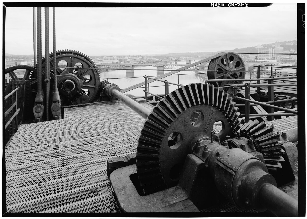
A rack and pinion is a gear pair in which the rack is effectively a gear of infinite radius, so the pinion's pitch circle rolls along a straight pitch line and converts rotation into linear travel. That one geometric fact is why every rule governing parallel-shaft gears — module, pressure angle, undercut, backlash, contact pattern, hardness — applies to a rack drive as well, and why treating it as a catalogue item instead of a transmission usually ends in a noisy, short-lived axis.
This guide works through the four decisions that determine performance: the geometry that sets travel and strength, the backlash budget, the mounting stiffness that quietly overrides tooth accuracy, and the manufacturing route.
How a Rack and Pinion Drive Works
The rack's pitch line is straight and the pinion's pitch circle rolls along it without slip, so one pinion revolution advances the rack by the pinion pitch circumference. Travel per revolution is therefore set by the pinion alone — designers who tune the rack or carriage during commissioning are usually fixing a problem created when the pinion size was chosen.
Metric geometry is compact: pitch diameter is d = m·z, with module m fixed by tooth size and tooth count z by the ratio. A standard full-depth profile uses an addendum of about 1.0m, a dedendum of about 1.25m and a whole depth near 2.25m, with exact values taken from the governing standard rather than assumed.
Force follows from the same pitch line. Pinion torque produces a tangential force of about 2T/d at the pitch point, and that is what pushes the rack; the radial force acts along the line of centers and tries to separate pinion from rack, so bearings, housing and mounting carry a load that grows with pressure angle.
Tooth Geometry: Module, Pressure Angle and the Undercut Limit
A 20-degree pressure angle is the common modern choice for spur rack and pinion systems, but it is a convention rather than a requirement. Higher angles raise bending capacity and separating load while making the mesh less sensitive to center-distance error; lower angles run smoother at the cost of a thinner root.
Undercut is the first geometry limit most designers meet. For a standard 20-degree full-depth pinion the nominal no-undercut limit sits near 17 teeth, and a smaller pinion is not automatically disqualified: profile shift or altered proportions can permit fewer teeth, but the result must be checked by calculation because the root thins and contact ratio drops. Treating 17 as a hard minimum is as wrong as ignoring it.
Rack tooth form is a separate decision. A straight-tooth rack is simple to mount and carries no axial load, which makes it the default for general machinery. A helical rack engages gradually, so more teeth share load at any instant and the drive runs smoother and quieter; the price is an axial thrust component that needs a thrust bearing or opposing hand, and a face that is harder to seat flat. Where racks butt end to end, cut the joint in a tooth space and control pitch error across it, or the pinion registers an impulse at every pass and wears a band.
Backlash: Where It Comes From and How to Budget It
Backlash is intentional clearance between the non-working flanks. It absorbs manufacturing variation, elastic deflection, thermal expansion, lubricant film and contamination, and a zero-clearance design is not a practical default: it risks binding, overheating and acute sensitivity to dirt. The useful question is which item in the budget is allowed to consume the clearance.
| Source | How it appears | Control lever |
|---|---|---|
| Tooth-thickness allowance | Lost motion that reverses with direction | Set on the drawing from load, temperature and speed budget |
| Center distance error | Lost motion roughly 2·tan(alpha) times the offset | Bore position tolerance, shimmed or adjustable mount |
| Rack straightness, joint pitch error | Local tight spots, periodic error once per joint | Straightness limit, joint cut in a tooth space |
| Bearing and shaft compliance | Lost motion that grows with load, absent at no load | Bearing preload, shaft section, housing stiffness |
| Thermal growth difference | Clearance changes from cold start to running | Material pairing, clearance set hot |
| Wear in service | Clearance grows over life | Case depth and hardness, lubrication, sealing |
Center distance is the contributor people underestimate. For a 20-degree pressure angle, increasing center distance by Δa adds roughly 2·tan(20°)·Δa of backlash normal to the flank, about 0.73 times Δa. A 0.05 mm mounting error therefore costs about 0.036 mm of lost motion, which on a precision axis can exceed the entire allowance — the arithmetic reason bore position tolerances appear on rack drawings.
Anti-backlash arrangements buy lost motion back in exchange for something else. A split or spring-preloaded pinion keeps both flanks in contact; opposed pinions do the same with more hardware; an eccentric or wedge-adjusted mount trades adjustment range for stiffness. Each adds cost, assembly time or friction, and excessive preload simply moves the wear to flanks and bearings. Positioning error is also not backlash alone: tooth-spacing and profile error, transmission error, bearing clearance, rack straightness and guide error contribute, and several of them scale with load while backlash does not.
Rack Support and Mounting Stiffness
A rack is a beam, not a rigid line. Under tangential load it deflects between fasteners, which changes the effective center distance locally, pushes load onto the ends of the contact band and raises local contact stress. The visible result is a rack that wears in patches and a drive that gets louder as load rises, with tooth accuracy that measured perfectly on the bench.
The countermeasures are ordinary machining discipline: a machined seat with declared flatness, a fastener pitch chosen so rack deflection under rated load stays small against the backlash budget, support along the full length rather than at the ends, and rack and guide rail on the same datum. Guide misalignment tilts the pinion and loads one flank preferentially. Steel stiffness sets the scale — roughly 200 to 210 GPa modulus and 7.8 to 7.9 g/cm³ density — and no surface hardening changes it, so a soft mount with hard teeth is still a soft drive.
Materials, Hardness and Lubrication
Loaded steel sets normally use alloy steels with carburized, nitrided or induction-hardened tooth surfaces; published heavy-duty practice cites 18CrNiMo7-6 for both rack and pinion, with the case specified by depth and surface hardness rather than by alloy name. Hardened gear materials can reach approximately 58 HRC or higher after suitable heat treatment, but that value belongs to a specific alloy and process chain and should not be generalized.
A harder tooth is not automatically a stronger tooth. Surface hardness buys wear and contact-fatigue resistance, while bending strength depends on core toughness, case depth, root fillet geometry and freedom from grinding damage. A deep case on a thin root raises distortion and cracking risk; a shallow case on a loaded flank wears through and spalls. Lubrication decides how much survives: open racks need grease plus a wiper or cover where chips, dust or coolant reach the tooth band, because contaminated grease becomes an abrasive paste — and a dry-running rack belongs in light-duty, low-speed service only.
Manufacturing Routes: Machining, Powder Metallurgy and MIM
Machining is the flexible route: milling, hobbing, shaping and broaching cover any length and tooth form, and grinding afterwards is what makes a cut rack a high-accuracy one. Cycle time scales with size and precision, so machining is natural for prototypes, long racks, unusual helix angles and repair work. Powder metallurgy suits high-volume, repetitive near-net gears, but residual porosity lowers effective strength, ductility and fatigue resistance, so any capability claim has to be tied to a stated density and material condition rather than to the process name.
Metal injection molding sits at the small, complex, high-volume end. Feedstock of fine metal powder and binder is molded, debound and sintered to 95-99% of theoretical density, with a size window of 0.1-200 g and walls of 0.5-6 mm — enough for small pinions with integrated hubs, keyways and bosses that would otherwise need several machining setups. Dimensional change during debinding and sintering is compensated in the tool and confirmed on a trial shot.
The limits deserve stating plainly. Long structural racks with through-hardened teeth are not recommended for MIM: rack length works against mold size, and straightness over long sections through a sintering furnace is difficult to hold. Nor does near-net shape mean no secondary operations — MIM pinions routinely receive sizing, bore machining or tooth grinding, and as-sintered tolerance of ±0.3-0.5% of nominal (about ±0.025 mm under 3 mm) tightens to approximately ±0.01 mm only on treated features.
| Route | Best fit | Tolerance reality | Where it fails |
|---|---|---|---|
| Machined and ground | Prototypes, long racks, unusual tooth forms, repair | Set by machine and finishing; grinding improves tooth accuracy | Unit cost scales with length and precision |
| Powder metallurgy | High-volume repetitive gears sized for pressing | Shrinkage and density gradients; sizing may be needed | Porosity caps ductility and fatigue capability |
| Metal injection molding | Small complex high-volume pinions | Shrinkage is a process variable; tool compensation essential | Not for long racks; straightness and distortion over length |
Specifying a Set: The Drawing Checklist
A rack and pinion drawing that can be inspected states: module; pinion tooth count and rack pitch-line length; pressure angle; helix angle and hand where applicable; accuracy grade by a published system such as ISO 1328 or AGMA; backlash as a range at a stated center distance and temperature; required contact pattern; tooth-thickness method (span or over-pins); rack straightness and seat flatness; joint position; material with heat treatment, case depth and hardness range; flank finish; and lubrication provision.
Remove two phrases before release: "no backlash", and "clear and legible" applied to markings. Neither is verifiable at goods-in. Replace them with a numeric range and a measurement method, and agree the contact pattern at first article rather than during ramp-up.
Frequently Asked Questions
Q: How do I choose the module and pressure angle for a rack and pinion?
Size the module from tangential load and allowable tooth bending stress with a margin for shock, then confirm contact ratio and undercut at the chosen tooth count. A 20-degree pressure angle is the common default and a sensible starting point, not a rule: higher angles raise bending capacity and separating force, lower angles run smoother and load bearings less.
Q: How much backlash should a rack and pinion have?
There is no universal value. Set a range at a stated center distance and operating temperature, derived from the tolerance and deflection stack, the thermal environment, speed and the accuracy the axis must hold. Lightly loaded positioning drives need little; heavily loaded, hot or contaminated systems need more. A drawing that says only "minimal backlash" transfers the decision to whoever assembles the drive.
Q: Can metal injection molding produce rack and pinion gears?
For pinions, often yes when the part is small, complex and the volume justifies a mold: MIM covers 0.1-200 g and 0.5-6 mm walls, holds ±0.3-0.5% as-sintered and tightens to about ±0.01 mm on sized or ground features. For long structural racks it is not recommended, since mold size and straightness through debinding and sintering both work against it. A MIM pinion running against a machined rack is a realistic combination.
Q: How much lost motion does a center distance error create?
For a 20-degree pressure angle the mesh gains approximately 0.73 mm of backlash per millimetre of center-distance increase, since sensitivity is about 2·tan(20°). A 0.05 mm housing offset therefore costs roughly 0.036 mm of extra clearance, which is why bore position tolerance rather than tooth quality alone often dominates a precision axis.
Q: Why is my rack wearing on one flank only?
One-sided wear points at alignment or preload rather than at the teeth. Check pinion-to-rack squareness and the guide-to-rack datum, then the contact pattern under load: if marking sits toward one end of the face width, the rack seat or pinion housing is tilting. Anti-backlash preload applied in one direction keeps one flank working continuously, which is normal but shortens that flank's life.
A rack and pinion drive is a gear pair with a straight pitch line, so the design work is the familiar one — geometry, backlash budget, stiffness, hardness, lubrication — done at the drawing stage and verified at first article. The drives that fail in the field rarely have the wrong module; they are the ones whose mounting seat was never toleranced and whose backlash allowance was never written down.
If you are sourcing a pinion, a short rack segment or a complete linear axis, send the drawing and duty cycle: Emitech reviews small and mid-size gear parts for MIM suitability alongside machined alternatives, and the recommendation comes back with the quotation through the contact page. Related reading: MIM small gears, the MIM gears manufacturing guide, and ring gear geometry for internal-tooth drives.
Precision Metal Parts from Emitech
Nanjing Emitech delivers MIM, CNC machining, and custom metal parts. MIM services · Request a quote