

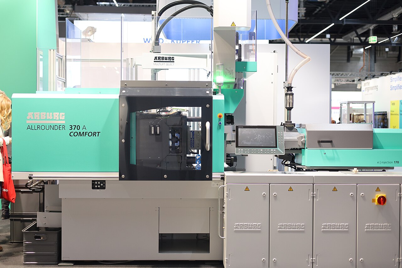
Yes, MIM supports insert molding, but with a constraint plastic molding never faces: the assembly must survive debinding and sintering together, often above 1,200 °C in some stainless systems. A solid metal insert does not shrink, while the surrounding MIM body contracts by roughly 14–22% linearly, so the interface is loaded by shrinkage and CTE-mismatch stresses in every cycle. A true co-sintered metallurgical bond is possible when surface condition, chemistry, and the thermal cycle are engineered for diffusion; otherwise the robust route is molding for mechanical retention, or joining after sintering.
This page lays out how insert molding works in metal injection molding, what actually controls bond integrity — CTE match, insert surface condition, shrinkage restraint, furnace atmosphere — and how to choose between co-sintering, mechanical retention, and post-sinter joining. It closes with the validation tests that separate a metallurgical bond from a trapped insert.
How Insert Molding Works in MIM
In plastic injection molding, insert molding is routine: an insert is placed in the tool and the polymer is injected around it. MIM starts the same way — inserts are loaded into the cavity, the metal feedstock is injected around them, and the green part is ejected with the insert embedded. Everything after that is different: the assembly must pass through debinding and a sintering cycle that takes the MIM body to about 95–99% of theoretical density, while the insert, already solid, barely changes.
That asymmetry defines the engineering problem. Published MIM design guidance puts linear shrinkage during debinding and sintering at roughly 14–22%, commonly approximated at about 15–20% for initial estimates, and the actual value is feedstock-, orientation-, and furnace-dependent. The insert anchors the shrinking body the way a stake anchors soil: stress concentrates at the interface, and whether it produces a clamp-tight joint or a cracked shoulder depends on decisions made long before the first firing. The full debind-sinter sequence is described on the MIM process page; this page concentrates on what happens at the insert interface.
Insert Materials and CTE Matching
The first screen is thermal: the insert must survive the MIM sintering cycle without melting, slumping, or growing coarse grains. For stainless and low-alloy MIM systems that cycle often runs above 1,200 °C, which is why inserts are usually a wrought or machined metal similar to the feedstock alloy — a 316L body around a 316 insert, or 17-4PH around 17-4PH. Same-family pairing keeps thermal expansion close and avoids galvanic couples in service.
But thermal matching alone settles little. Interface stress grows roughly in proportion to the CTE difference, the elastic constraint, and the temperature change — and a matched CTE still does not establish a bond, because plasticity, creep, porosity, and any interlayers change the outcome. Treat CTE as a screening filter, not a specification.
| Consideration | What to check | Why it matters |
|---|---|---|
| CTE difference | Keep insert and feedstock alloys in the same family where possible | Mismatch stress scales with CTE difference and temperature swing; the insert also constrains 14–22% matrix shrinkage |
| Sintering survival | Insert softening and stability vs sintering temperature (often above 1,200 °C in stainless systems) | An insert that creeps or slumps in the furnace loses both geometry and clamping |
| Chemistry | Avoid couples that form brittle intermetallics or galvanic pairs | Interface embrittlement surfaces only in mechanical or corrosion testing |
| Furnace atmosphere | Oxide behavior of the insert in hydrogen, N2/H2, or vacuum cycles | A stable oxide film blocks metallic contact and diffusion bonding |
| Supply state | Cleanliness and any plating or coating as delivered | Plating can act as diffusion barrier or helper interlayer — it must be intentional |
When a dissimilar pairing is unavoidable — a stainless body around a carbon-steel pin, for example — a thin interlayer can mediate diffusion. Published inserted-MIM research has evaluated nickel coatings of 10 μm, 20 μm, and 30 μm on steel inserts, with the beneficial thickness remaining application-specific. Interlayer options and insert process parameters are quoted on request with the project review.
What Actually Creates the Bond in Co-Sintering
Co-sintering can produce a genuine diffusion-assisted metallurgical joint: as the MIM body densifies, mating surfaces approach closely enough for diffusion across the interface. The mechanism is closer to solid-state bonding than to adhesive joining, and continuity across the interface is process- and material-specific rather than automatic. Shrinkage itself cuts both ways — matrix contraction can press the interface closed, but the same contraction, resisted by the insert, can distort, shear, or crack the assembly.
Temperature is the strongest lever. In one reported 17-4PH co-sintering study, interfaces fired at about 1,245 °C stayed weak and leaked under pressure, while raising the cycle to about 1,370 °C produced pressure-resistant joints. That window should not be generalized to other alloy pairs — higher temperature also drives grain growth, distortion, and loss of dimensional control — but it shows how narrow a usable co-sintering window can be.
- Surface condition is a primary variable: oxide films, residual binder, handling contamination, and plating defects block metallic contact even when the alloys are compatible.
- Intimate contact in the green state is necessary but not proof of contact after firing; debinding and shrinkage can open or shift the interface.
- Knurls and undercuts add mechanical interlock; they do not create diffusion bonding and do not substitute for metallurgical validation.
- Furnace atmosphere and dew point control how oxides on both mating surfaces are reduced before diffusion can start.
Tooling and Insert Placement
The mold side of insert molding carries its own rules. Inserts must be located positively — on locating pins, in pockets, or against seats that survive injection pressure — because a shifted insert is scrap after firing, not before. The feedstock must fully surround the insert with enough wall to avoid thin sections that crack during shrinkage; the standard MIM production window of 0.5–6 mm wall thickness applies around the insert as well.
Loading method drives cost: hand-loaded inserts slow the cycle and cap the sensible cavity count, while tooled loading with in-mold detection protects repeatability. Every insert also adds a potential flash path at the insert interface and a maintenance item in the tool — insert tooling is reviewed and quoted on request with the mold quotation.
Design the interface deliberately: shallow knurls or flanges for mechanical retention when the joint is mechanical by design; smooth, clean, maximum-contact surfaces when the objective is diffusion bonding. Grooves that trap binder residue become defect sources during debinding. The wider tooling and DFM context is covered in the DFM guidelines for MIM and CNC.
Validating Bond Integrity
A co-sintered insert must be qualified against the failure mode that matters in service — tensile or shear separation, leak tightness, torque or pull-out resistance, fatigue, thermal cycling, corrosion — because a single room-temperature pull test covers none of the others. Validation should compare insert and MIM materials before and after the full thermal cycle, using dimensional inspection, cross-sectional metallography, porosity assessment at the interface, and a mechanically relevant test at the intended temperature where applicable.
Metallography is the arbiter of any “metallurgical” claim: a cross-section shows whether porosity, oxides, or unbonded gaps line the interface. In mechanical testing, interfacial failure means a trapped insert; cohesive failure through the MIM matrix indicates a sound joint. Leak tightness is a separate criterion — a pressure-tight interface is not proof of full metallographic continuity, and the two acceptance criteria should not be conflated. Interface test scope and acceptance criteria are set case by case and quoted on request.
Co-Sinter or Join After Sintering?
The honest default is that joining after sintering is usually the lower-risk route, and co-sintering has to earn its place. Post-sinter joining — welding, brazing, press-fitting, or threaded assembly — lets each component be processed at its own optimum, inspected before assembly, and reworked if a joint fails; the cost is a second process step. See welding MIM parts and MIM secondary operations for that side of the decision.
| Route | Bonding mechanism | Best suited when | Watch-outs |
|---|---|---|---|
| Direct co-sintering | Diffusion-assisted metallic interface plus geometric restraint; requires validation | Same-family alloys, clean surfaces, cycle engineered for bond development | Narrow thermal window; distortion and cracking risk from shrinkage restraint |
| Co-sinter with mechanical retention | Knurls, flanges, and undercuts carry the load; any diffusion is a bonus | Load path is defined and retention geometry fits the part | Not a metallurgical bond; validate pull-out and torque directly |
| Interlayer-assisted co-sintering | Plated or foil interlayer (e.g. nickel) mediates diffusion | Dissimilar pairings that otherwise will not bond | Thickness and process are application-specific; adds a supply step |
| Join after sintering | Weld, braze, press, or thread the components post-furnace | Risk-averse programs, dissimilar materials, joints that need inspection or rework | Second operation cost; joint design differs from monolithic geometry |
As a rule of thumb: specify co-sintering when the assembly cannot be joined afterwards (sealed internal cavities, inaccessible interfaces), when volumes justify developing the thermal window, and when the alloy pairing is same-family. Specify post-sinter joining when materials differ, when each part needs its own heat treatment, or when the joint must be inspectable and reworkable.
Frequently Asked Questions
Q: Can a metal insert be co-sintered with a MIM part?
Sometimes. Compatibility depends on the insert's composition, surface condition, thermal expansion, and dimensional stability through debinding and sintering — often above 1,200 °C in some stainless systems. Same-family pairings such as 316L with 316, or 17-4PH with 17-4PH, are the usual starting point, and the resulting bond must be validated metallurgically rather than assumed.
Q: How much does the MIM body shrink around an insert?
Roughly 14–22% linearly, commonly approximated at about 15–20% for first estimates, and the value is feedstock-, orientation-, and furnace-dependent. Because the insert does not shrink, the matrix is restrained locally: the tool must compensate around the insert, and the interface must be designed for the resulting stresses rather than for nominal contact.
Q: What CTE mismatch is acceptable between insert and MIM material?
There is no universal acceptable mismatch. Interface stress grows roughly with the CTE difference, the temperature change, and the elastic constraint, but plasticity, creep, porosity, and interlayers all change the result. CTE matching is a screening filter: a matched CTE does not establish a bond, and a moderate mismatch can be survivable with retention geometry.
Q: How do you test whether an insert is bonded or just trapped?
Cross-sectional metallography shows whether the interface is continuous, porous, or lined with oxide; a mechanically relevant test — pull-out, torque, shear, or fatigue at service temperature — shows where failure runs. Interfacial failure means a trapped insert; cohesive failure through the MIM matrix indicates a sound joint. Leak tightness is a separate criterion and does not prove metallographic continuity.
Q: When is insert molding in MIM not recommended?
Avoid co-sintering when the insert cannot survive the furnace cycle (melting, heavy oxidation, distortion), when the alloy pair forms brittle intermetallics, when the joint must be inspectable or reworkable, or when shrinkage restraint around a rigid insert would crack thin surrounding walls. In those cases, mold the body plain and weld, braze, or press-fit afterwards.
Insert molding in MIM is a real capability with a narrow engineering window: the furnace decides the bond, not the mold. If you have an assembly in mind — a threaded bushing in a stainless body, a hardened pin in a latch component — send the drawing through the contact page: Emitech reviews the insert pairing, retention geometry, and joining route together, and returns a quotation within 24 hours.
Precision Metal Parts from Emitech
Nanjing Emitech delivers MIM, CNC machining, and custom metal parts. MIM services · Request a quote