
As-sintered MIM parts are not reliably pressure tight: they sinter to 95–99% of theoretical density, and the residual porosity can form a connected path through the wall. Whether a specific component holds a specific leak rate is component-, alloy-, and process-dependent, so tightness has to be specified and verified per part rather than assumed from the material. The engineering answer is a process decision — seal the porosity (resin impregnation), close it (HIP on suitable geometries), design around it (sealing lands on machined or sized faces), or accept a quantified leak rate the part actually meets. Density alone does not predict the result, because leakage follows the largest connected pore path rather than the average porosity.
This guide covers the engineering sequence in the order it matters on a drawing: how porosity creates leak paths, what an as-sintered part can realistically hold, the three routes to a tight part and their trade-offs, how to choose between pressure decay and helium mass-spectrometer testing, and how to write an acceptance criterion a supplier can actually measure.
How Sintered Porosity Creates Leak Paths
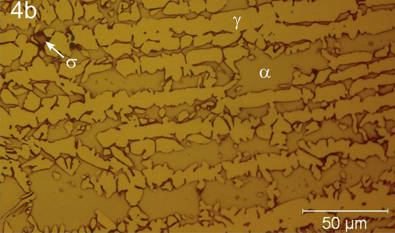
Sintering densifies a powder compact by diffusion, not by melting. Emitech MIM parts typically reach 95–99% of theoretical density, and the balance is porosity distributed through the section. That range is normal and is why MIM parts approach wrought mechanical properties without matching them; it is also the origin of every leak-tightness question on this page.
The engineering distinction is between isolated and interconnected porosity. Isolated pores lower strength, ductility, and fatigue life but do not conduct gas. Interconnected pores form tortuous channels that can run from one surface to the other, and a part may pass a short bulk pressure test while still containing a continuous micro-path that shows up later under a more sensitive method or a different fluid.
Leakage is governed by the largest connected path, not by average density or total porosity. Two parts from the same lot at nominally similar density can therefore have materially different leak rates, which is why a density certificate is not a tightness certificate. The pore-scale mechanisms are covered on the MIM density and porosity page; this page stays with the leak consequence.
- Incomplete sintering or a cold spot in the furnace leaves necks between particles that never closed.
- Debinding residue, carbon pickup, or oxide films can pin open porosity along a section.
- Local density gradients from gate position, flow length, or wall-thickness transitions concentrate porosity in one band.
- Shrinkage mismatch between thick and thin sections can open a micro-gap at the transition.
- Machining and grinding after sintering can expose a pore network that was closed at the as-sintered surface.
What an As-Sintered Part Can and Cannot Hold
As-sintered MIM is not a pressure-tightness process, and it is not recommended to specify a low leak rate on an as-sintered surface without agreeing on a sealing route first. A short proof-pressure test proves behavior at one pressure and duration; it is not a quantified low-leak-rate measurement and should not be reported as one.
What the process does deliver reliably is geometry and tolerance: as-sintered tolerances of ±0.3–0.5% of nominal dimension (about ±0.025 mm on features under 3 mm), with sizing and CNC secondary operations reaching approximately ±0.01 mm on the treated faces. Part mass runs 0.1–200 g with walls of 0.5–6 mm. Tolerance and tightness are separate acceptance criteria and should be written separately.
The practical consequence is that a leak requirement must name the condition of the part it applies to — as-sintered, after impregnation, after HIP, after machining, or after assembly. A requirement that says only "pressure tight" leaves both the method and the process state to the supplier, and two honest suppliers will then measure two different things.
Three Routes to a Pressure-Tight Part
Hot isostatic pressing attacks the porosity itself. Applied to a suitable MIM component, HIP can reduce or close internal porosity, but the outcome depends on pore morphology, the gas state inside the pores, the alloy, the surface or encapsulation condition, and the cycle used. It should not be assumed to remove every connected path without component-specific validation — that work is described on the MIM with HIP page.
Resin impregnation fills connected pores with a sealant and is the most common route for moderate tightness at moderate cost. It is a trade-off rather than a repair: it changes the material system, and the sealant brings its own temperature capability, chemical compatibility, outgassing, and cleanability limits. Subsequent machining, coating, welding, or thermal cycling can reopen or degrade a sealed path, so the impregnating material and process belong on the drawing whenever leak performance depends on them.
The design route avoids the problem instead of treating it. Put the sealing land on a machined or sized face rather than an as-sintered surface, keep the land in a thicker section so local density is high, and define flatness and surface finish on that land. A gasket or O-ring land designed this way often removes the need for impregnation altogether.
| Route | What it changes | Best suited to | Watch-outs |
|---|---|---|---|
| As-sintered design | Nothing — seal land placed on a machined or sized face | Moderate differential, ambient temperature, gasket or O-ring joint | Requires a defined flatness and finish on the land; adds a secondary operation |
| Resin impregnation | Fills connected pores with a cured sealant | Moderate tightness, thin walls, parts that must stay dimensionally stable | Temperature and chemical limits of the sealant; outgassing; later machining can reopen a path |
| HIP | Closes or reduces internal porosity in the metal | Parts that also need fatigue or ductility gains | Depends on pore morphology and encapsulation; needs component-specific validation; added cost and lead time |
HIP and impregnation are not interchangeable: HIP changes the metal's internal structure, while impregnation fills voids with a secondary material. Their effects on strength, corrosion resistance, temperature capability, and leak behavior all differ, so the choice should be driven by the service condition, not by whichever route is quoted first.
Leak Testing: Matching the Method to the Limit
Pressure decay measures the change in gas inventory over time and is the workhorse production method. Published guidance puts practical sensitivity at about 10⁻³ mbar·L/s, with roughly 10⁻⁴ mbar·L/s reachable only in favorable, well-controlled setups, and real capability depends heavily on test volume, temperature stabilization, transducer resolution, fixture leakage, and trapped gas. Report a calculated leak rate rather than a pressure drop, otherwise the number is not comparable between fixtures or shifts.
Helium mass-spectrometer testing adds sensitivity, though how much depends entirely on the configuration: practical helium accumulation, sniffer, and vacuum methods span roughly 10⁻⁵ to 10⁻⁹ mbar·L/s, and reaching 10⁻¹⁰ or lower generally requires an optimized laboratory setup rather than a production fixture. That can be from about one order to several orders better than pressure decay. The result is method-specific: tracer concentration, test pressure, stabilization time, fixture background, and calibration all move the reported value, and a helium rate is not automatically equivalent to an air or service-fluid rate.
Selection follows from the acceptance limit. Leak-testing guidance such as NASA-STD-7012A requires the test system to be verified with a calibrated standard leak and the detection capability to be demonstrated; the engineering corollary is to show a detection limit comfortably below the allowable rate before the method is accepted, and to make that margin explicit in the requirement. If the required limit sits below what pressure decay can resolve reliably, helium is the honest choice; if the limit is loose, pressure decay is faster and cheaper to run in volume.
| Method | Typical sensitivity | Best suited to | Limitations |
|---|---|---|---|
| Pressure decay (air or N₂) | About 10⁻³ mbar·L/s typical; 10⁻⁴ only in favorable setups | High-volume production screening with a loose to moderate limit | Sensitive to test volume, temperature drift, fixture leakage, trapped gas |
| Helium vacuum test | Roughly 10⁻⁵ to 10⁻⁹ mbar·L/s practical; ≤10⁻¹⁰ needs an optimized lab setup | Tight limits, safety-related sealing, R&D validation | Method-specific result; background and calibration dominate; slower per part |
| Helium sniffer / accumulation | Higher detection limit than vacuum helium | Line testing where the part cannot be evacuated | Draft and background effects; needs a calibrated reference leak to stay honest |
How to Write the Leak-Tightness Requirement
"Sealed" is not an acceptance criterion. A measurable requirement names the test fluid, the test pressure and direction, the temperature, the stabilization time, the allowable leak rate with units, the test method, the calibration requirement, and the process step at which the test applies.
- Fluid and direction: air or nitrogen from the inside out, or helium either direction — state it, because the flow regime differs.
- Test pressure and hold time: the differential across the wall, plus how long the part stabilizes before the reading.
- Allowable leak rate with units: mbar·L/s or sccm, with the gas species and pressure it refers to.
- Method and sensitivity: pressure decay with a stated resolution, or helium mass spectrometry with a stated detection limit and calibration standard.
- Process state: as-sintered, after impregnation and cure, after HIP, after machining, or after assembly — and whether the seal survives later operations.
- Sampling: 100% test for safety-related sealing, or a defined AQL where the consequence of a leak is contained.
A workable drawing note reads like this: "Leak test 100% with helium mass spectrometer, 2 bar differential, allowable leak rate 1×10⁻⁶ mbar·L/s max (subject to the demonstrated detection limit of the chosen method and fixture), detector calibrated with a certified standard leak, test after impregnation and cure and before assembly." Every clause in that sentence is measurable, which is the whole point.
When MIM Is Not the Right Answer
MIM is not recommended for parts that must satisfy a pressure-vessel code as a monolithic body, or where burst strength, fatigue life, and long-term sealing all have to be qualified from a single as-sintered process. Those duties belong to wrought or cast bodies with certified section properties, or to a MIM part used as a non-pressure-retaining component inside a proven housing.
Avoid using impregnation as a substitute for structural density where the part also carries load or sees repeated thermal cycling: the sealant restores tightness, not the metal that was missing. Equally, avoid writing a helium-level limit on a part that will be machined after testing, because the machined surface exposes new porosity that the test never saw.
Where the duty is moderate — a sensor housing, a valve body at low differential, a fluid manifold at ambient temperature — a MIM body with a machined seal land, or with validated impregnation, is usually the lower-cost answer. The MIM quality misconceptions page covers the common failure modes that get blamed on the process when they are really specification gaps.
Frequently Asked Questions
Q: Can as-sintered MIM parts be pressure tight?
Only in the sense that a specific component can be shown to meet a specific leak rate — it is not a property you can assume from the material. As-sintered MIM retains porosity that may be interconnected, and whether a given part holds a given rate depends on alloy, geometry, and sintering history, so a leak requirement should be specified together with a sealing route and verified by test. A short proof-pressure test is not a substitute for a quantified leak measurement.
Q: Does 98% density mean the part will not leak?
No. Leakage follows the largest connected pore path, not average density, so two parts at similar density can differ in leak rate by orders of magnitude. Density is a material certificate value; tightness has to be measured on the part with the method and limit named on the drawing.
Q: Should I specify impregnation or HIP?
Choose by service condition. Impregnation is lower cost and suits moderate temperature and moderate differential, but the sealant brings chemical, outgassing, and temperature limits and can be reopened by later machining. HIP changes the metal itself and can also improve fatigue and ductility, but it costs more and its effect on a connected path must be validated per component.
Q: Is pressure decay testing enough, or do I need helium?
It depends on the allowable leak rate. Pressure decay resolves about 10⁻³ mbar·L/s in typical production setups, and around 10⁻⁴ only under favorable conditions, so if your limit is tighter than that, helium mass spectrometry is the honest method. Verify the test system with a calibrated standard leak and show that its detection limit sits comfortably below the acceptance limit; many programs work to an internal margin of around 10%, but that margin is a specification choice rather than a fixed rule.
Q: How should a leak requirement appear on the drawing?
As a full sentence with fluid, differential pressure, temperature, stabilization time, allowable leak rate with units, method, calibration, and the process step it applies to. Requirements written as "sealed" or "leak proof" cannot be accepted or rejected objectively.
Leak tightness is a specification problem before it is a manufacturing problem: once the fluid, the differential, the allowable rate, and the process state are written down, the route — as-sintered design, impregnation, or HIP — usually selects itself. If you have a MIM component with a sealing duty, send the drawing and the service conditions through the contact page; Emitech reviews the seal land, wall section, and post-sintering sequence and returns a quotation within 24 hours.
Precision Metal Parts from Emitech
Nanjing Emitech delivers MIM, CNC machining, and custom metal parts. MIM services · Request a quote