

The metal injection molding process has four stages, and the reason it works is that the first two borrow a plastics technique and the last two pay for it. Feedstock compounding, injection molding, debinding and sintering — ASTM specifications describe this sequence for ferrous MIM, and each stage has a failure mode that the next one cannot fix.
Most explanations stop at naming the stages. This one explains what each stage is actually controlling, which numbers are published and which must be qualified on your own feedstock, and which widely quoted claims about MIM do not survive inspection.
Stage 1: Feedstock Compounding
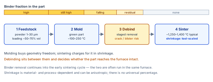
Feedstock is a moldable mixture of fine metal powder and a multicomponent binder system — that definition is ASTM's, and both halves matter. The powder provides the final material; the binder provides everything the powder cannot do on its own, which is flow. Powder loading commonly sits in the range of about 50% to 70% by volume of metal, with the exact figure driven by powder morphology, particle-size distribution, binder chemistry and the shrinkage the process is designed to produce.
The powder itself is fine: particle sizes are often on the order of 1 to 30 μm, which is finer than conventional press-and-sinter grades because the powder has to flow through small gates at high loading. That fineness is also why MIM powders carry more surface oxide per unit mass and why sintering atmosphere matters so much later.
Compounding is where two failure modes originate. Poor dispersion leaves binder-rich and powder-rich regions, which mold differently and sinter differently. A loading that is too high for the binder system raises viscosity past what the machine can fill reliably; too low and shrinkage rises and the green part sags. Neither problem can be corrected downstream.
Stage 2: Injection Molding the Green Part
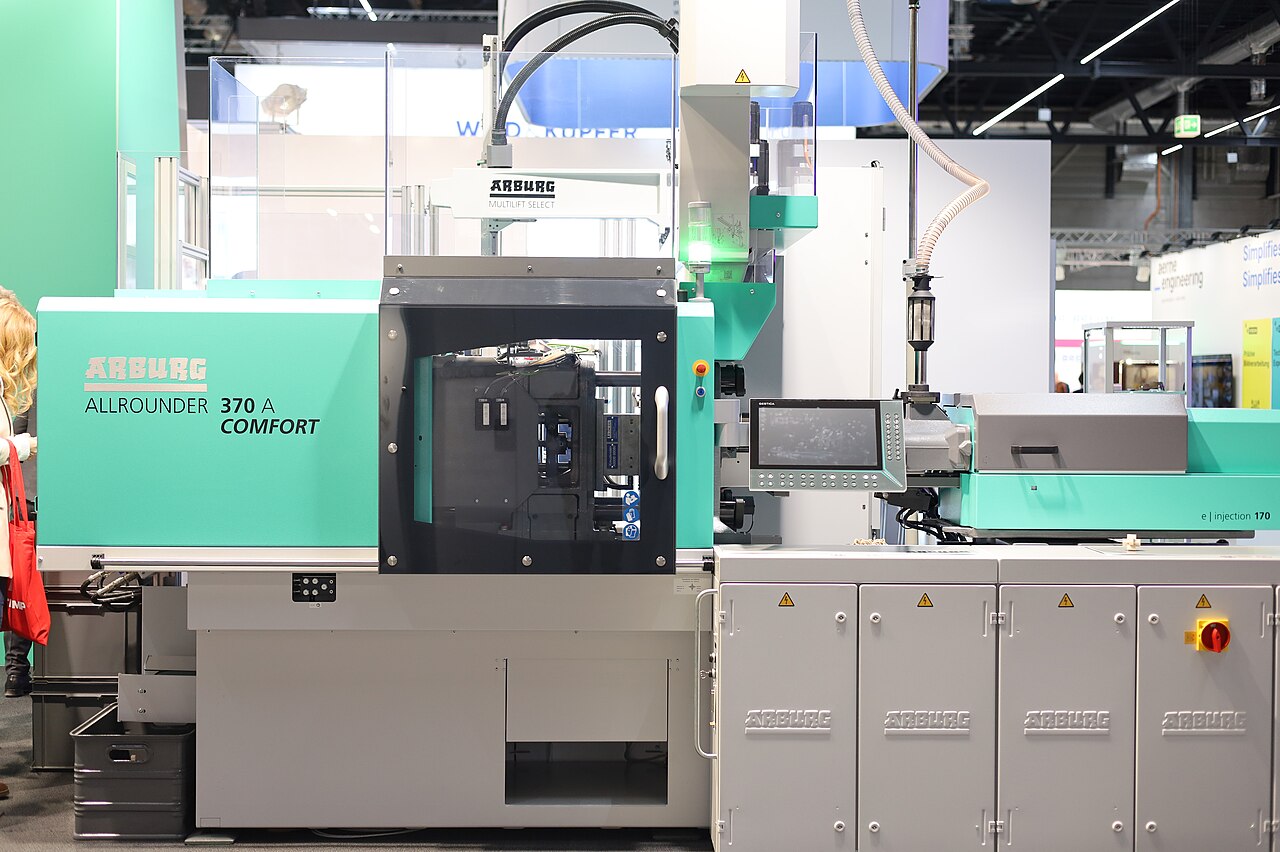
Molding produces a green part that holds the molded geometry and contains substantially more binder than the finished component. Feedstock is heated until the binder supplies enough flow to fill the cavity — molding temperatures commonly fall in the region of about 100 °C to 250 °C, a range that is entirely dependent on the binder formulation rather than on the metal.
Filling is controlled by injection pressure, screw speed, mold temperature, feedstock temperature and hold pressure. There is no universal pressure or temperature window across MIM feedstocks, and the same machine settings applied to a different feedstock lot will not reproduce the part. Gates, runners and the defects they cause remain process-dependent rather than properties of the technology.
This is the stage where MIM looks easiest and is most deceptive. The part looks finished. What has actually been produced is a fragile, oversized, binder-heavy shape that will shrink substantially and that must survive two more stages without cracking — and the molding conditions set up how well it does that.
Stage 3: Debinding — Removing Most of the Binder
Debinding is the intermediate operation between molding and sintering in which the majority of binder is extracted, by heat, solvent, catalytic reaction or another technique. It commonly runs in stages: a readily removable primary or backbone component comes out first, followed by thermal removal of the residual fraction.
The reason for the staged approach is mechanical. While binder is leaving, the part is a porous metal skeleton held together by whatever binder remains. Remove too much too fast and the part cracks, blisters or slumps; remove too little and the residual binder contaminates the sintering atmosphere and blocks densification. The removal rate has to stay ahead of the part's tolerance for losing its own scaffolding.
One common misdescription is worth correcting: debinding is not simply burning the binder out, and in many MIM routes the binder is removed thermally under reducing or inert conditions where combustion is not the intended mechanism. Another: debinding does not remove all the binder before sintering begins. Residual binder removal generally continues during the early part of the sintering cycle, which is why the two stages are often run in the same furnace.
Stage 4: Sintering and the Shrinkage That Pays for Stage 2
Sintering takes the now-porous skeleton to near-final density. The powder particles bond by diffusion, necks grow, pores round and shrink, and the part consolidates. MIM typically sinters hotter than conventional press-and-sinter — often in the region of 1,250-1,400 °C with many standard materials near the top of that band — because the fine powder and the need for high density both push the window up.
The cost of molding instead of pressing is shrinkage: substantial, and it must be built into the tool. The frequently quoted figure of exactly 15% in every direction is a simplification that does not hold — shrinkage is material- and process-dependent and can be anisotropic, which means a single universal factor applied to every geometry will produce out-of-tolerance parts.
Density is the other number to treat carefully. MIM reaches high density, and the claim of always 99% to 100% of theoretical is not supported: density varies with alloy, powder, loading, furnace cycle and the specification being applied, and qualified parts can retain residual porosity even at high density.
| Stage | Main control variables | Typical published values | Failure mode it owns |
|---|---|---|---|
| Feedstock compounding | Powder morphology and size distribution, binder chemistry, solids loading | Powder commonly 1-30 μm; loading about 50-70% by volume | Binder-rich or powder-rich regions; viscosity outside machine capability |
| Injection molding | Injection pressure, screw speed, mold and feedstock temperature, hold pressure | Molding temperature often about 100-250 °C, binder-dependent | Short shots, weld lines, gate and runner defects, molded-in stress |
| Debinding | Removal mechanism, staged hold temperatures, ramp rate | Formulation-specific; no universal hold temperature | Cracking, blistering, slumping from too-fast removal; residual binder from too-slow |
| Sintering | Peak temperature, hold time, atmosphere, heating and cooling rate | Often about 1,250-1,400 °C for MIM; alloy-specific | Distortion from shrinkage, grain growth, carbon drift, residual porosity |
After Sintering: Secondary Operations and Heat Treatment
Optional heat treatment follows sintering where the alloy and application need it — for example ageing 17-4 PH or hardening certain tool steels. Beyond that, sizing, machining, surface finishing and inspection may still be required, which is the direct answer to the claim that MIM eliminates all secondary operations: it eliminates many, not all.
Sizing is the standard route when a dimension needs to be tighter than as-sintered tolerance. It is also the honest explanation for how MIM parts reach drawing tolerances that the base process does not hold directly — and why a tolerance conversation should include a secondary operation and its cost, rather than assuming the sintered state delivers it.
What the Process Fits, and What It Does Not
MIM suits small, complex, high-volume metal parts that would otherwise be machined from solid or assembled from several pieces: the geometry freedom is the selling point, and the tooling cost is the entry fee. It does not suit very large parts, very thick sections, low volumes, or alloys that are difficult to process into fine powder and sinter.
Thick sections are the most commonly underestimated limit. They raise debinding time and distortion risk faster than they raise anything else, so practical limits are binder- and geometry-specific rather than a published maximum wall thickness.
Within our own line the equipment — 17 MIM injection machines, 13 debinding furnaces and 22 sintering furnaces across continuous and vacuum designs — sets what can be scheduled, while the material and the part geometry set the window itself. Cycle parameters for a specific part are quoted on request rather than published as a generic recipe.
Frequently Asked Questions
Q: What are the four stages of the metal injection molding process?
Feedstock compounding, injection molding, debinding and sintering, with optional heat treatment and secondary operations afterwards. ASTM specifications describe this sequence for ferrous MIM. The first two borrow plastics processing; the last two exist to convert the molded shape into metal, and the shrinkage during sintering is the price paid for the molding freedom.
Q: What is MIM feedstock made of?
A moldable mixture of fine metal powder and a multicomponent binder system. Powder loading is commonly about 50-70% by volume, with powder particle sizes often on the order of 1-30 μm. The binder supplies flow during molding and is then removed in stages; the powder supplies the final material.
Q: How much does a MIM part shrink during sintering?
Substantially, and it varies. Shrinkage is material- and process-dependent rather than a fixed percentage in all directions, and it can be anisotropic. That is why the shrink factor is built into the tool for a specific material and geometry and confirmed on a trial shot, rather than copied from a generic figure.
Q: Why does debinding have to be slow?
Because while binder is leaving, the part is a porous metal skeleton held together by what remains. Removing binder faster than the decomposition products can escape causes cracking, blistering or slumping; removing too little leaves residual binder that contaminates the sintering atmosphere and interferes with densification. The rate has to stay inside that window, which is formulation- and section-thickness-specific.
Q: Does MIM produce parts with no porosity?
No. MIM reaches high density, and the level varies with alloy, powder, loading and furnace cycle. Qualified parts can retain residual porosity even at high density, and claims of guaranteed 99-100% theoretical density across the board are not supported by the process literature.
The metal injection molding process is a trade: molding buys geometry freedom, and sintering charges for it in shrinkage that must be designed into the tool. Debinding sits between them as the stage that decides whether the part arrives at the furnace intact.
Reading the four stages as one chain — where compounding sets the flow, molding sets the shape, debinding sets the survival odds, and sintering sets the dimensions — is what makes the process predictable. For a specific alloy or geometry, the qualified cycle and shrink factor are established on a trial part and quoted on request.
Precision Metal Parts from Emitech
Nanjing Emitech delivers MIM, CNC machining, and custom metal parts. MIM services · Request a quote